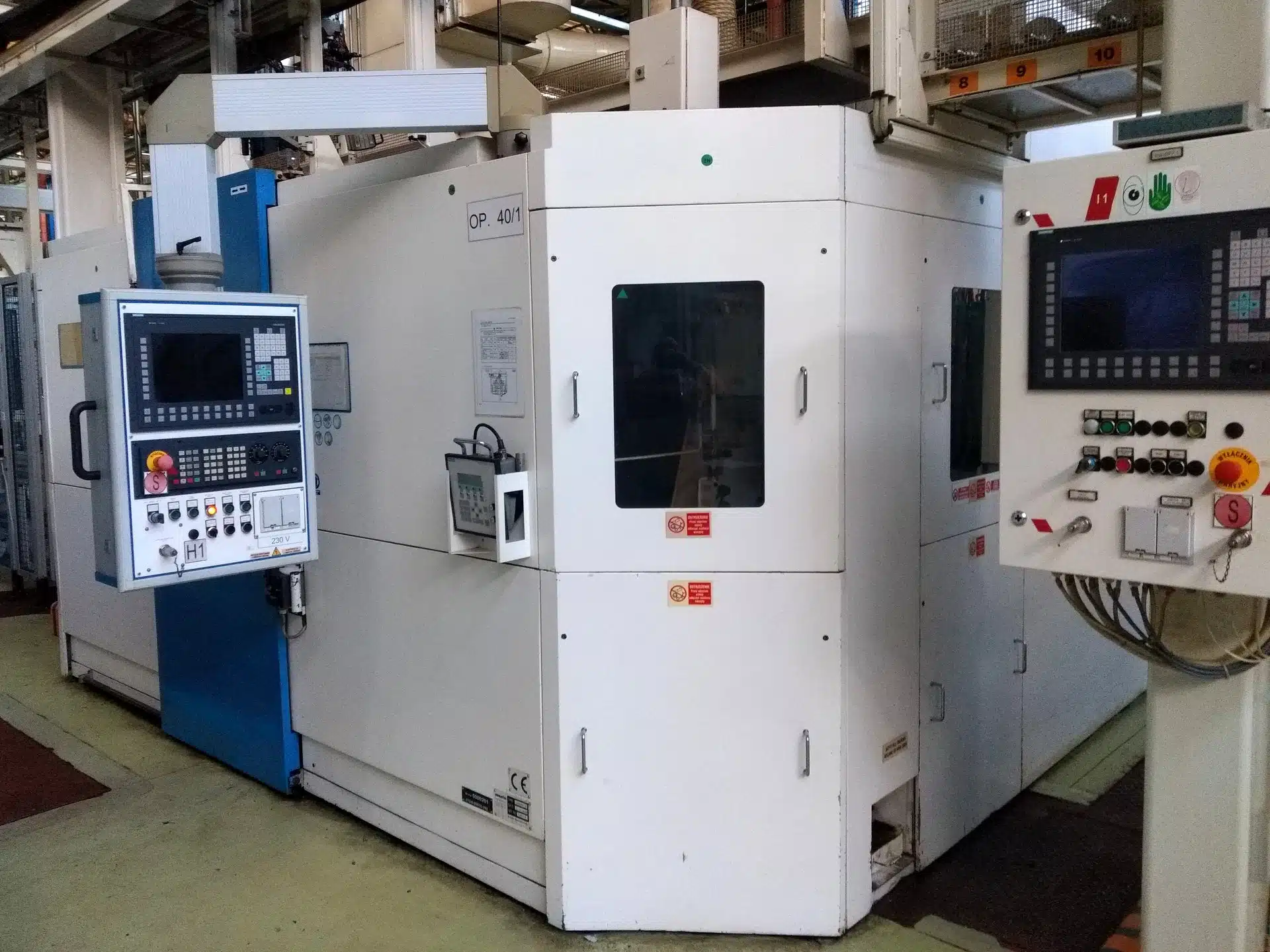
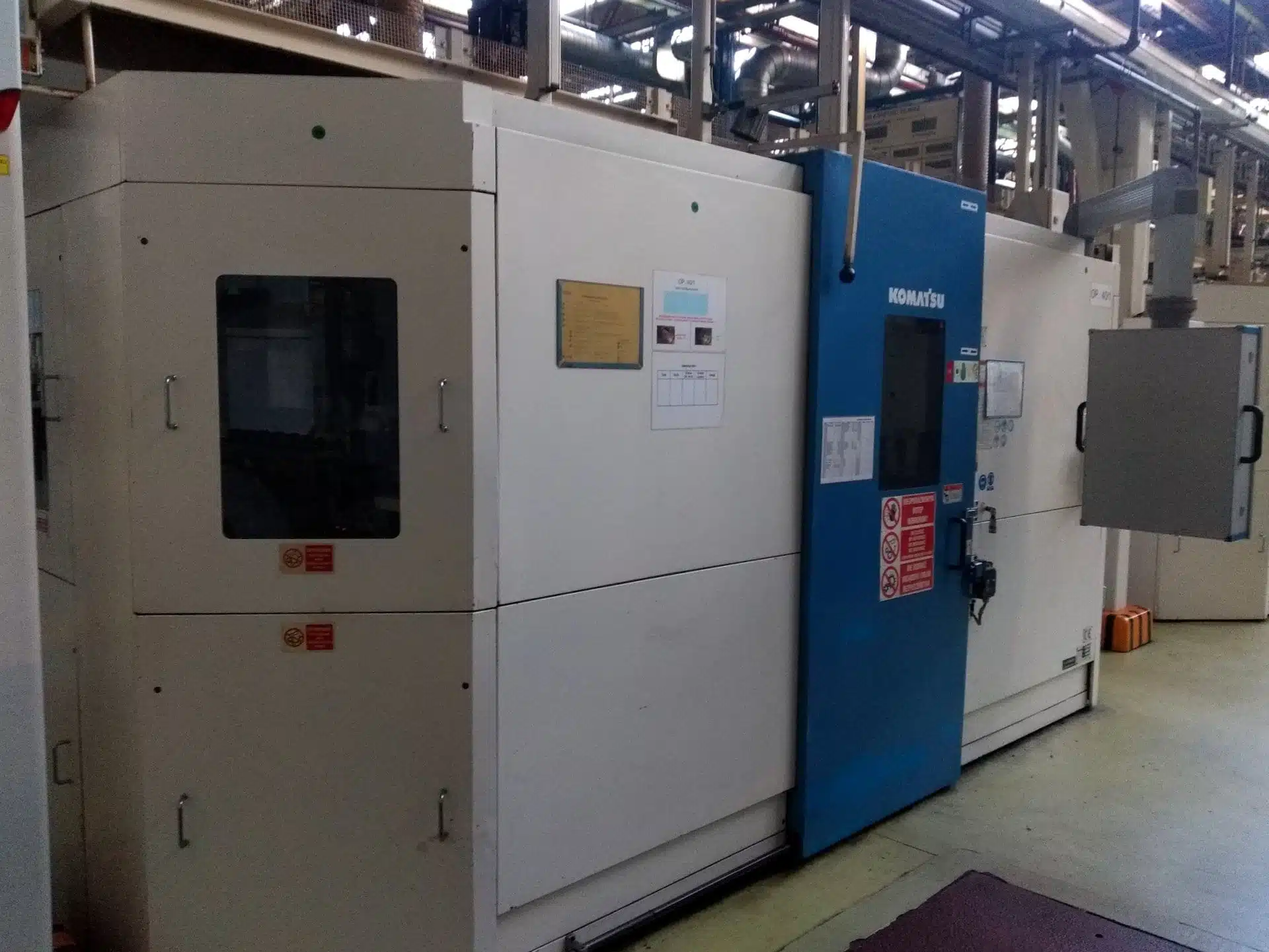
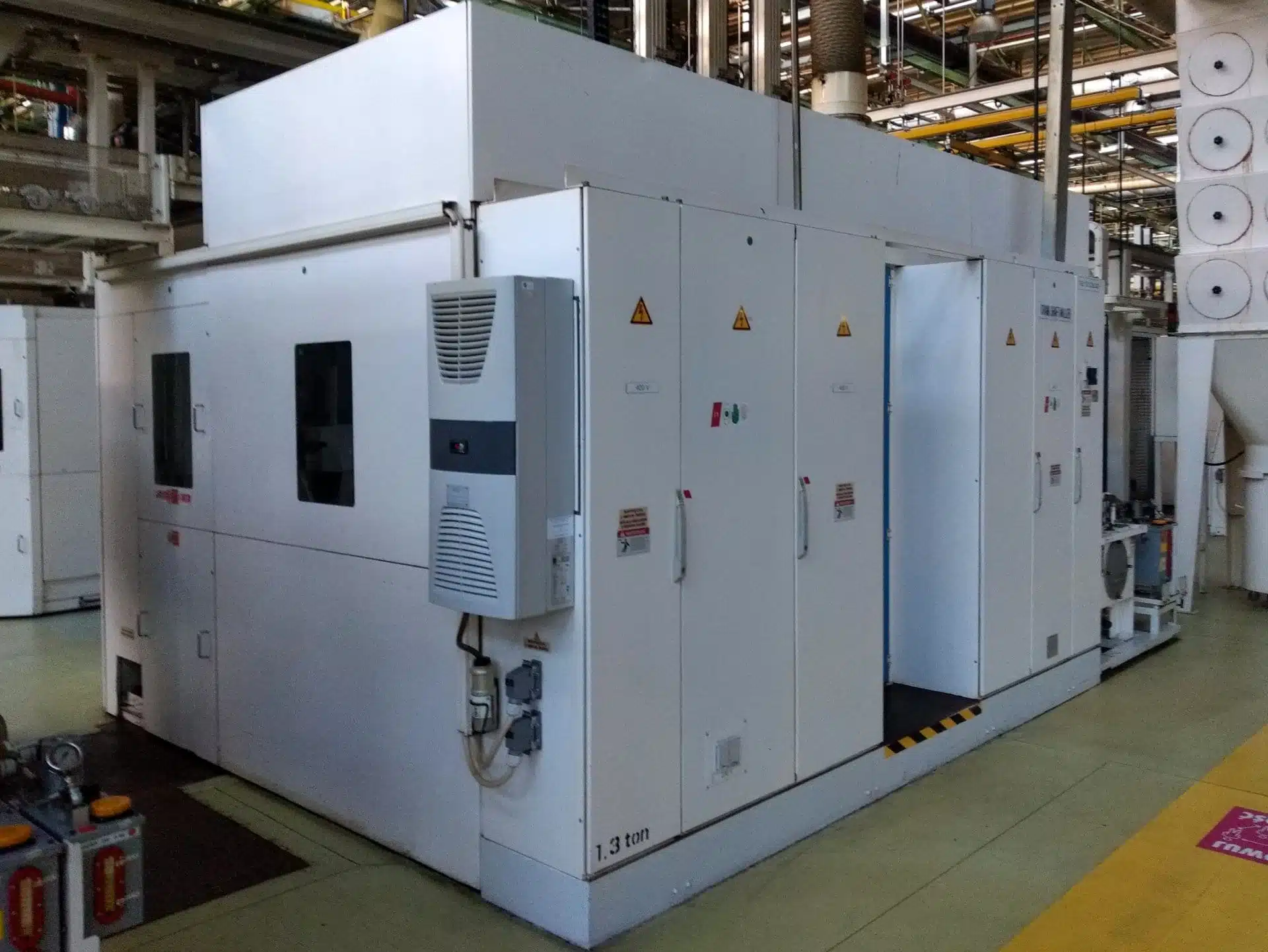
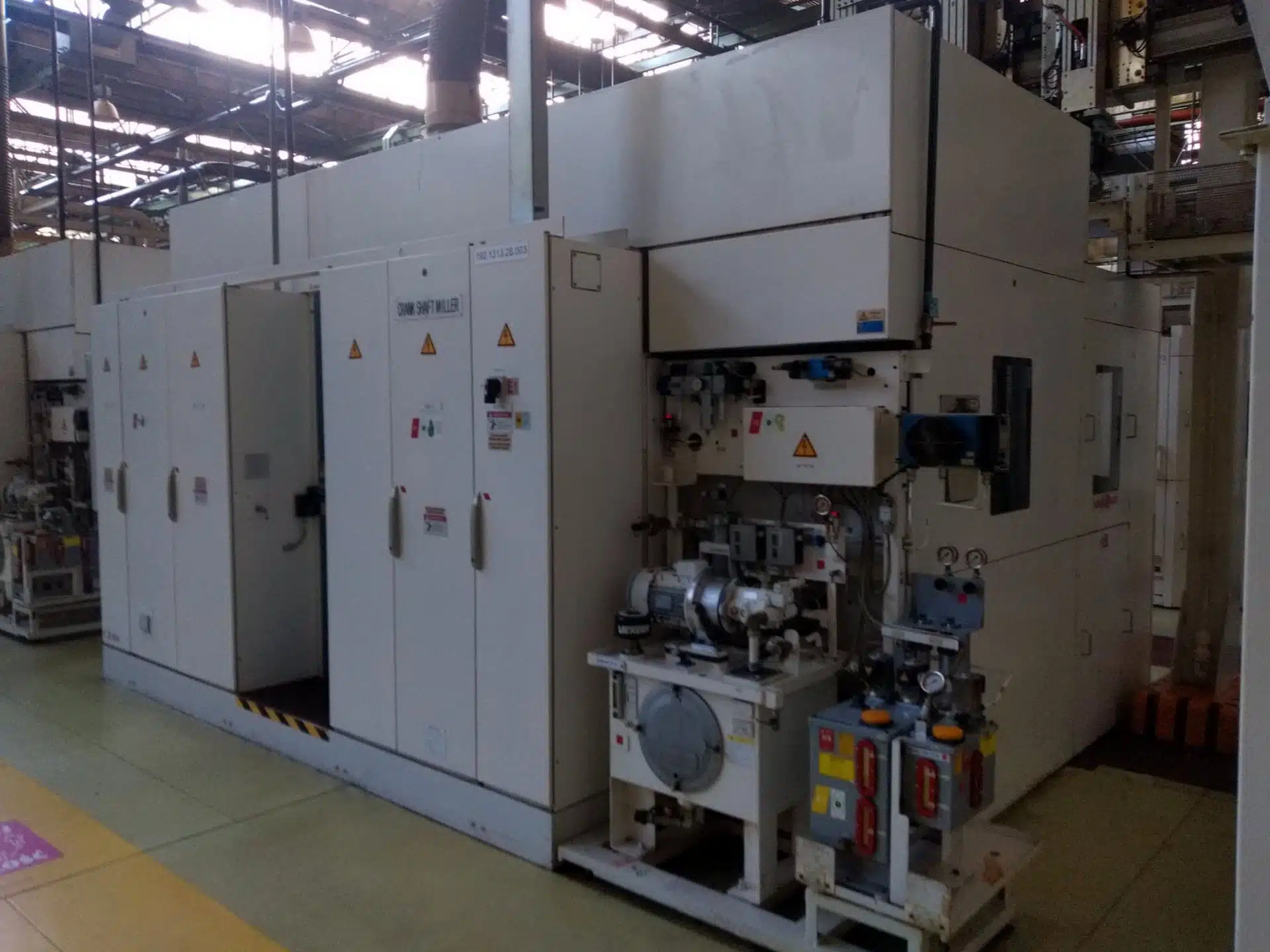
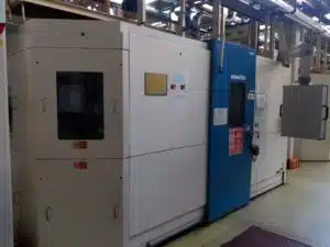
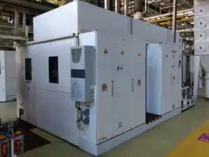
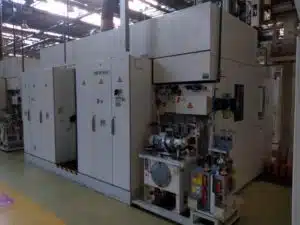
The KOMATSU GPM 200F2-3 CNC crankshaft machining center was manufactured in 2002 in Japan. The machine is designed to machine crankshafts with a maximum length of 700 mm. The cross slide moves longitudinally on the bed guides by means of an AC (alternating current) actuator. The working head on which the handle is mounted is permanently screwed to the bed. The chuck has a centering triple jaw in a cast steel housing, which acts with a clamping force of 80 kN. The machine steady rest prevents vibration and therefore enables stable machining while the workpiece is being cut. The crankshaft milling machine has six axes (X1, X2, Y1, Y2, Z1, Z2) with maximum feeds of +/- 172.5 mm (for X1 and X2 axes), +/- 95 mm (for Y1 and Y2 axes) and +/- 450 mm (for Z1 and Z2 axes). The axes have a SIEMENS 1FT6 actuator with an Absolute brake and are computer controlled by a SIEMENS Sinumerik 840D CNC controller. Rapid feeds in the X, Y, Z axes are respectively 12040 mm/min, 6700 mm/min and 14400 mm/min. The machine spindles rotate at 188 rpm. The GPM 200F2-3 machining center weighs 26,000 kg.
Specifications of CNC crankshaft milling machine KOMATSU GPM 200F2-3
– CNC control: SIEMENS Sinumerik 840D
– number of controlled axes: 6
– maximum detail length: 700 mm
– minimum eccentric diameter: 210 mm
– minimum diameter of the main journal: ƒ50 mm
– height of the chuck center: 1280 mm
– maximum feed in axes:
X1: +/- 172.5 mm (tool center 95 mm)
X2: +/- 172.5 mm (tool center 95 mm)
Y1: +/- 95 mm
Y2: +/- 95 mm
Z1: +/- 450 mm
Z2: +/- 450 mm
– maximum rapid feed in the axes:
X: 12040 mm/min
Y: 6700 mm/min
Z: 14400 mm/min
– X, Y, Z axis actuator: SIEMENS 1FT6 with an brake Absolute
– number of spindles: 2
– spindle motor power: 37 kw
– spindle speed: 188 rpm
– cutting speed 142 m/min
– tool diameter: 240 mm
– workpiece steady
– workpiece head (2 pcs.)
– hydraulic unit tank capacity: 100 l
– voltage: alternating current, 3-phase, 380V +/- 10%, 50Hz +/- 1Hz
– machine height: 2950 mm
– total weight of the GPM 200F2-3 machine: 26 t
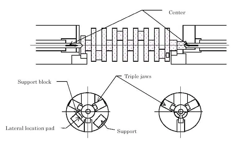
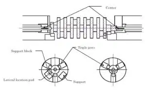
Clamping movements in the chuck of the crankshaft milling centre
1. The crankshaft is loaded on the support locks in the holders,
2. The fangs approach the centerline of the handle on both sides,
3. The crankshaft is pushed against the side support washer,
4. There is a check if the part is well pressed (checking the seating of the part),
5. The triple jaws finally come closer to clamp the part with its main trunnion and collar.
