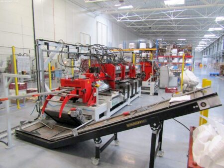
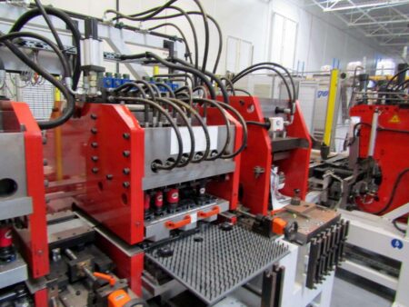
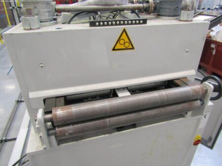
The WEMO sheet metal line was produced in 2008 by the Dutch company WEMO Nederland BV This machine is designed for serial production of strip elements (sheet in a coil) in an automatic cycle, e.g. panels for computer case, electric cabinet case panel, panels for coffee machine case etc. (elements are visible in the attached photos). The line for the production of sheet metal elements includes, among others, such workstations as sheet unfolding, straightening machine, punching station or bending station.
The production line with bending and punching stations can be used wherever it is necessary to automate production, in which we have the operation of punching, stamping, punching and bending.
The WEMO sheet metal line consists of the following workstations
1. Sheet decoiler (coil tape)
2. Straightener
3. Punching station
4. Bending station
5. Parts collection station
6. Hydraulic control
7. Electric control
1. Sheet decoiler (coil tape)
– max coil weight: 1500 kg.
– spindle extension range: approx. 480 – 530 mm
– outer diameter of the coil: 1400 mm
– side vertebra guide
– self-centering hydraulic
– support arms (2×3) manually adjustable.
– holding the arm: pneumatic
– Electric drive: forward, reverse or freewheel
– Disc brake: springs
– Coil loading: front by crane or lift truck.
– Machine base: fixed
2. Straightener
– Belt speed 2-10 m / min, continuously adjustable
– 7 straightening rollers Ø 40 mm
– 2 pulling rollers Ø 40 mm
– Spacer straightener rolls 60mm
– Machine frame: welded structure
– Rollers: hardened, ground and hard chrome plated
– Retractable rollers: Locking the top roller opens manually (hinges).
– Adjustment of the upper feed roller: manually, reading on a ruler
– Side tape guide: Entry side left / right centrally adjustable manually on a ruler
– Loop control: ultrasound
– Drive: from both the pull-out rollers and the lower straightening rollers by means of a frequency-controlled three-phase motor ensuring continuous straightening progress
3. Sheet punching station
– Consists of a welded steel machine frame with fixed or adjustable feed rollers, C presses, cutting unit and belt guides.
– There is a roller basket supporting the belt at the ramp.
– The sides of the belt are guided on guide rollers, which are centrally cross-adjusted by means of a threaded spindle and a knob, reading on a mechanical counter.
– After cutting, the product goes to the bending station.
– The waste will fall into the bin.
– Standard Thick Turret Tool Presses have additional spare inputs available for specific type production.
This station is mounted
3.1 Roller feeder: with 2 feed rolls ø60 mm. – Feed rollers: hardened, ground and hard chrome plated.
– Upper roll adjustment: pneumatic.
– Belt feeding: by driving both feed rolls.
– Drive: by NC motor.
– Input + programming: setting the feed length and speed by measuring
circle.
3.2 Belt guides centrally adjustable manually by hand wheel and L + R threaded mandrel.
3.3 1 + 1 Hydro-C Press, 400 mm throat depth for (almost) all tool entries. The presses are mounted on guide rails and are separately shifted in depth by the NC motor program.
The press has individually driven hydraulic cylinders.
3.3.1 Press no. 1 with a tonnage of 5×2.5 and 4×4.5.
3.3.2 Press no. 2 with a tonnage of 4×8, 2×12.5 and 1x 16.5. The two 8 tonnes and one 12.5 tonnes entry also have a cylinder for stamping tools at the bottom.
3.1 1 + 1 empty die set, throat depth 400 mm for (almost) all tools. In this set the tools (Mate) can be changed manually.
3.5.1 Die set 1 was placed in the press 3.3.1. The holder allows max. 5x type A and 4x type B tools. 3.5.2 Die set 2 was placed in the press 3.3.2. The holder allows max. 4x Type C, 2x Type D and 1x Type E Mate.
3.2 1 Hydro portal press with 2 entrances.
– Inlet width 1 = 195 mm, inlet width 2 = 245 mm
– Both with pressure plate with column post guide.
– Permanently mounted at the end of the punching station.
– 450 mm transition – Input 1 is with a 16.5 ton cylinder on top and 12.5 tonne below, so discharge
can be done up.
– Input 2 has a 40 ton cylinder on top. Head / tail severing tools are placed here.
3.3 1 Portal tool type 195×450 with column guide. With this tool, the handles are embossed in the side panels.
3.4 1 Portal tool type 195×300 with column guide. This tool punches the head / end of the intermediate panel also the first head bend + 90 ° l = ± 133 mm) is bent upwards. The scrap after punching is approx. 5 mm. This tool is in position 2 of the press 3.8.
3.5 1 Portal tool type 195×450 with column guide. With this tool, punch holes in the head / tail of the right side panel. The scrap after punching is approx. 5 mm. The tool is placed in position 2 of the press 3.8.
3.6 1 Portal tool type 195×450 with column guide. This tool punches the head / tail of the left side panel. The scrap after punching is approx. 5 mm. The tool is placed in position 2 of the press 3.8.
3.7 1 Portal tool type 95×300 with column guide for straight cuts of approx. 5 mm. The tool is placed in position 2 of the press 3.8. By means of the lift springs in the die plate, the back wall is lifted so that the imprints of the “raster” are lifted down over the die.
3.8 1 Magnetic conveyor for transporting blanks. This system is pneumatically shifted in height.
3.9 1 + 1 side cutter for cutting the sides of the tape to size. The minimum cutting depth is 2 mm per side cutter (maximum 15 mm). Both cutters have a spring-loaded handle and a cylinder with a diameter of approx. 12.5 tons. There is an additional set of guides with pneumatic plate closers on the drive-in and out-side sides. The side cutters are mounted on guides in front of the roller conveyor and are manually adjusted in width with a handwheel.
3.10 2 Sets of hooks for changing tools.
– 1 set for both presses C.
– 1 set for a portal press pos. 3.5.
4. Longitudinal bending station
– In this station, the bender and the product manipulator are positioned opposite to each other.
– A magnetic conveyor feeds the blank to this station and reaches the head stop for length centering.
– The conveyors fall off and the blank is centered in width in relation to its edge.
– The manipulator then clamps the blank and places it in the bending machine. After the first side has been bent, the manipulator rotates the blank and the other side is bent without the need to re-center it.
– After the bending is completed, the clamping beam opens and the blank is placed on the magnetic conveyor in the center of this station and transported to the starting station.
This station is mounted
4.1 1 Bender type 2xR220-ZBU-C3, suitable for both upward and downward bending.
– Fixed beam and bottom bracket have 90 ° bend holes
which have already been made.
– The bending angle is controlled by electro-hydraulic bending angle adjustment,
corrected by the program.
– Hydraulic tandem cylinders control 3 positions of the bending beam.
4.2 1 Pneumatic head stop, manually adjustable longitudinally.
4.3 1 + 1 Pneumatic head stop manually adjustable in width by hand wheel with approx. 5 special limiting strips for centering the product width. Belts must be replaced manually.
4.4 Magnetic conveyor 1 + 1 for transporting blanks. This system is pneumatically shifted in height.
4.5 1 brush bed for supporting the product.
4.6 1 Product manipulator with NC rotary shaft and NC sliding shaft for product handling. Complete with 2 pneumatic door closers for centering the width.
4.7 1 Pneumatic unit for lifting (approx. 150 mm) an intermediate panel. The device is attached to the pressure beam of the bender.
4.8 1 Pneumatic backgauge for the last bend of the intermediate plate.
Changes are required when changing from one product to another:
– Sheet metal coil replacement
– Tool change (Mate tools)
– Belt width adjustment by hand wheel for two guide stations
– Product type adjustment: replacement of the support frame in the bender
– Finished products are transported on a roller conveyor (3 m) to the feeder and removed by the operator.

 Čeština
 Français
 Español
 Deutsch
 polski
 Русский
 Slovenčina
 Italiano


